Hvdraulicaccumulator action
An indispensable component in hydraulic and liguid technology. lt has many uses in the hydraulic circuit, such as1) saving driving power, 2) energy reserve; 3) attenuating pressure shock; 4) reducing pump pressure pulsation;5) keeping constantpressure.
The above functions can be carried out by the hydraulic accumulator, and thus can obtainspecial benefits, such as: increasingproduction capacity and total efficiency, improving its function, prolonging life,improving safety, reducing work and maintenance costs.
Operating Principle
Fluids are practically incompressible and cannot therefore store pressure energy.
The compressibility of a gas is utilised in hydraulic accumulators for storing fluids.
Diaphragm accumulators are based on this principle, using nitrogen as the compressible medium.
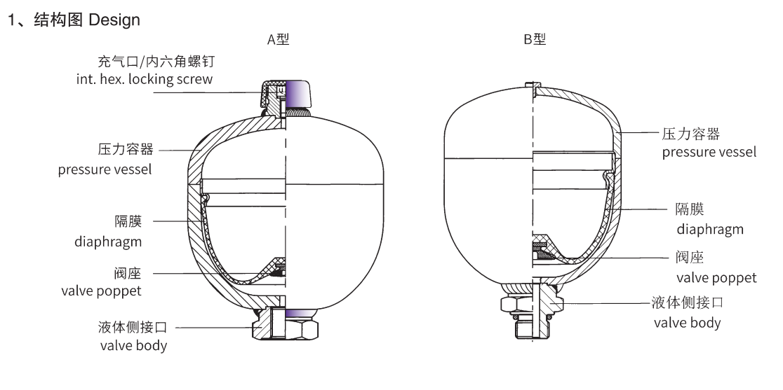
A diaphragm accumulator consists of a fluid section and a gas section with the diaphragm acting as the gas-prootscreen. The fluidsection is connected to the hydraulic circuit so that the diaphragm accumulator draws in fluid when thepressure increases and the gasis compressed. When the pressure drops, the compressed gas expands and forces the storetluid into the circuit. At the base of thediaphragm is a valve poppet, This shuts off the hvdraulic outlet when the accumulatoris completely empty and thus prevents damageto the diaphragm
Welded diaphragm accumulator structure

2、This consists of :
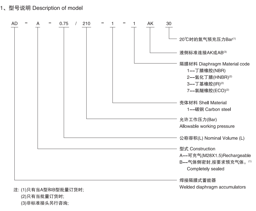
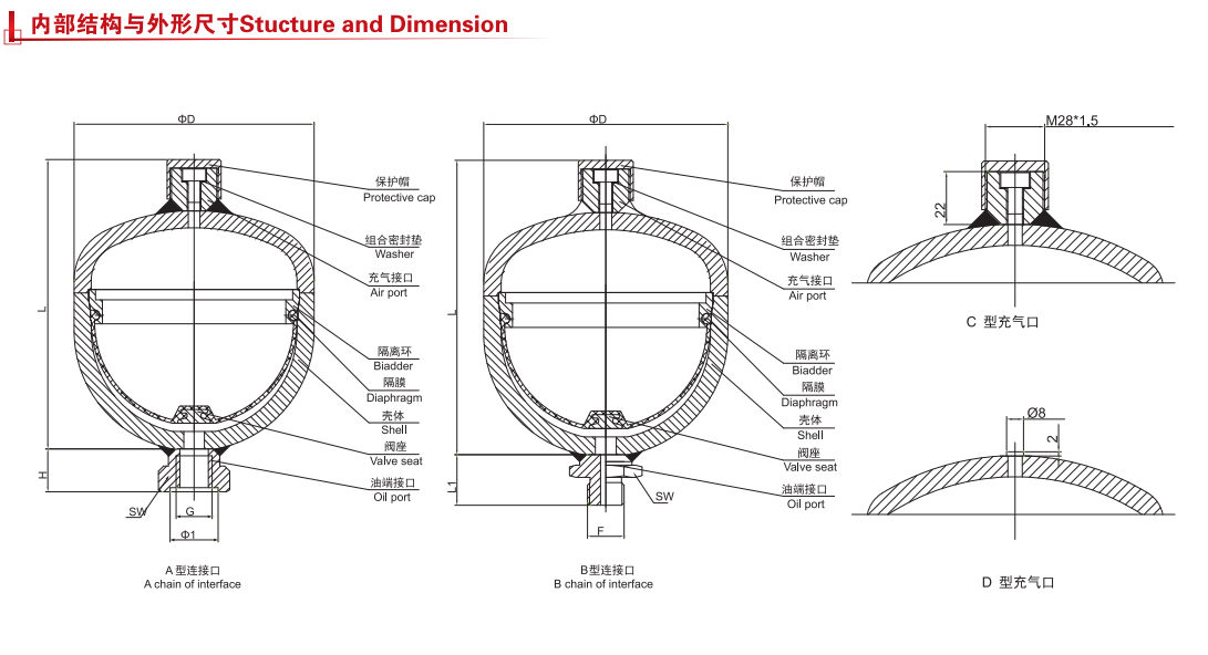
2.1 Welded pressure vessel, rechargeable on the gas side or, altermatively, completely sealed.
2.2 Fluid connection available in various types.
2.3 Exible diaphragm to separate the uid and gas sections.
2.4 Valve poppet set into the base of the diaphragm.
Diaphragm materials
The diaphragms are available in the following elastomers:acrylonitrile butadiene rubber PERB UNAN (NBR) , Hydrogenated nitrile (HNBR) ,ethylene oxide epichlorohydrin rubber(ECO) , butyl rubber (lR)The material must be selected according to the particular operating fluid and temperature.
Mounting Position
Optional. However, if there is a risk of contamination collecting, a vertical position is preferable fluid connection atthe bottom.
Type Mounting
Accumulators up to 2can be screwed directly inline.
Where strong vibrations are expected, the accumulator must be secured to prevent it working loose. For weld typaccumulators werecommend support clamps. Addiional male threads on the hydraulic connection are avallable forscrewing into mounting holes. Do noatach the accumulator to the hydraulic equipment by welding or mechanicaoperation. The hvdraulic pipe must be completelv deflatecafter connection.

Welded Diaphragm accumulator use steel stampingshell ,They have twotypesaccording to the gas side:Rechargeableand completely sealed.
2、GENERAL
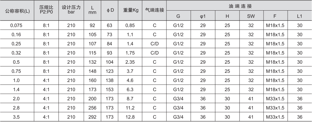
2.1 Permitted operating pressure (see tables 3.0)
2.2 Nominal volume(see tables 3.0)
2.3 Effective gas volume
Corresponds to the nominal volume of the diaphragm accumulator.2.4 Effective volume
Volume of fluid which is available between the operating pressures p,, and p,.2.5 Fluids
Mineral oils, hydraulic oils. Other fluids on request.
2.6 Gas chargingAll accumulators are supplied with a protective pre-charge. Higher gas pre-charge pressures are avallableon request (gascharging screw or sealed gas connection). Hvdraulic accumulators must only be charged with nitrogen,.Never use other gases.Risk oexplosion!
2.7 Permitted operating temperature
NBR:-20~+80℃ECO:-40~+80℃
HNBR :-20~+100℃
Others on request.
2.8 Permitted pressure ratio
Ratio of maximum operating pressure p, to gas pre-charge pressure p.
2.9 Max. flow rate of operating fluidin order to achieve the max. flow rate given in the tables, a residual fuid volume of approx, 109 of theetective aas volume mustremain in the accumulator.


Repair and maintenance
1. in order to work on the system equipped with an accumulator (maintenance, connection of pressure gauges, etc.,the ol pressure
must be released to zero.2. Test the inflation pressureReset afer each installation or overhaul and check the inflation pressure at least once during thefollowing week. lino nitrogen loss is detected, it can be done again afer three months check, if no change in infation pressure isfound,the detection period can be set to one year.
3. Repair, maintenance and commissioning personnel must be professionally trained.

